- 您现在的位置:买卖IC网 > Sheet目录221 > DPM125L (Martel Electronics)METER DPM LCD3.5DIGIT 200MV BKLT
Analogue inputs must be no closer than 1V to either the positive or negative supply.
Martel Electronics, Corp. P.O. Box 770 Londonderry, NH 03053
Toll Free: (800) 821-0023 Phone: (603) 434-1433 Fax: (603) 434-1653
PIN FUNCTIONS
1. DP1 199.9
2. DP2 19.99 Connect to V+ to display required DP.
3. DP3 1.999
4. TEST Connect to V+ to display segments as illustrated. It should not be operated for more than a few seconds as the d.c. voltage applied
to the LCD may 'burn' the display. This pin is normally at 5V below V+ and is the ground for the digital section of the meter. It can be
used to power external logic up to a maximum of 1mA.
5. V- Negative power supply connection.
6. V+ Positive power supply connection.
7. IN HI Positive measuring differential input.
8. INLO Negative measuring differential input.
9. COM The ground for the analogue section of the A/D converter, held actively at 2.8V (nom.) below V+. COM must not be allowed to sink
excessive current (>100 μ A) by connecting it directly to a higher voltage.
10. RLO Negative input for reference voltage (can be connected to COM via Link 3).
11. RHI Positive input for reference voltage (connected via Link 1 to ROH).
12. ROH Positive output from internal reference.
SAFETY
To comply with the Low Voltage Directive (LVD 93/68/EEC), input voltages to the module’s pins must not exceed 60Vdc. If voltages to the
measuring inputs do exceed 60Vdc, then fit scaling resistors externally to the module. The user must ensure that the incorporation of the
DPM into the user ’s equipment conforms to the relevant sections of BS EN 61010 (Safety Requirements for Electrical Equipment for
Measuring, Control and Laboratory Use).
V+ V+
V+ V+
+
IN HI
±200mV
+
IN HI
-
IN LO
-
IN LO
5 min. 5
V-
V+
IN HI
IN LO
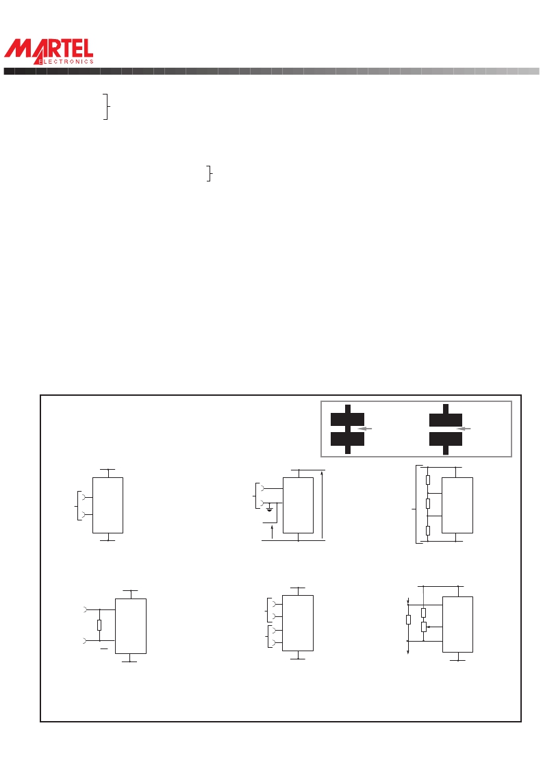
VARIOUSOPERATINGMODES
ON-BOARD LINKS: In order to quickly and easily change operating modes for
different applications, the meter has several on-board links. They are designed
to be easily cut (opened) or shorted (soldered).
Do not connect more than one meter to the same power supply if the meters cannot
use the same signal ground. Taking any input beyond the power supply rails will
damage the meter.
6 6
7
7
8
±200mV
8
0V
V- 1V V-
V-
Check Links 2 & 3 are SHORTED. Check Link 3 is SHORTED.
14V max
7V min
Normally
SHORTED
Cut to
OPEN
V+
6
510K
7
10K
SUPPLY
VOLTAGE 8
510K V-
5
V-
Check Link 3 is SHORTED.
Normally
OPEN
Solder to
SHORT
6
7
V+
+ 7 IN HI
8
- 10 REF LO
V-
7 V+
8
6R2
5K IN LO
COM
I OUT
V-
Measuringafloatingvoltagesource
of 200mV full scale.
V+
V+
+ IN HI
R -
- 8 IN LO
R=0.2
IF.S.R. V-
5 V-
Check Links 2 & 3 are SHORTED.
Measuring current. Supply MUST
be isolated.
Split supply operation.
6
V+
V 1
- IN LO
+ 11 REF HI
V 2
V-
5
Check Links 1 & 4 are OPEN.
Measuring the ratio of two voltages.
Reading = 1000 V 1 /V 2
50mV< V 2 <200mV
V 1 <2V 2 .
Measuring a supply voltage.
(min. 7.5V, max. 14V).
V+
I IN 6
IN HI
100K
SET
ZERO
9
V-
5
Check Link 3 is SHORTED.
Measuring 4-20mA to read 0-999.
(supply MUST be isolated).
Specifications liable to change without prior warning
DPM 125
Issue 3
August/1997
M.C.
Applies to DPM 125/2
发布紧急采购,3分钟左右您将得到回复。
相关PDF资料
DPM1AS-BL
LCD 5.5MM UNIV MINI METER BK LIT
DPM2000S
LCD DPM 5V/200MV 3.5 DIG S-RAIL
DPM2AS-BL
LCD 8.25MM UNIV MINI METR BK LIT
DPM35G
METER DPM LED 3.5DIGIT GREEN
DPM3AS-BL
LCD 11MM UNIV MINI METER BK LIT
DPM500SBL
METER DPM LCD 3.5DIGIT
DPM65S
METER DPM LCD SINGLE RAIL 200MV
DPM702S
PANEL METER LCD DL 200MV 3.5 DGT
相关代理商/技术参数
DPM160-4
制造商:RINO MECH.(GENGARELL 功能描述:
DPM160-8
制造商:RINO MECH.(GENGARELL 功能描述:
DPM16S56K-1F
制造商:Cornell Dubilier Electronics 功能描述:
DPM1750
制造商:Amphenol Corporation 功能描述:BLUE DUST CAP - Bulk
DPM1A0C9
制造商:OSLO SWITCH 功能描述: 制造商:Oslo Switch 功能描述:
DPM1AS-BL
功能描述:LCD 5.5MM UNIV MINI METER BK LIT RoHS:是 类别:工业控制,仪表 >> 仪表 - 面板,数字 系列:10 标准包装:12 系列:* 其它名称:Q7072030
DPM1N1191020
制造商:Pentair Technical Products / Hoffman 功能描述:Master, 19in,20A125V, 10outlet
DPM1N1662420
制造商:Pentair Technical Products / Hoffman 功能描述:Master, 66in,20A125V, 24outlet
